Sunday, March 29, 2009

Making the Attitude 1.5


Edge Products came into being during late 1999 and early 2000 with their Dodge Comp product. Later they built the Chevy product for the LLY engines. Their early products used a limited user interface. The Comp had a push button interface with an LED bar graph showing the power level.

One of the reasons that Edge Products were so big was the LCD display that they paired with their Juice products. The early displays were built using the Zilog 642120 processor. Zilog's processor is a RISC processor (Reduced Instruction Set). It's really quick and does a great job. One of the problems that this processor had was the memory was limited to only 64k. For approximately two years during the time when the display was in production, Edge Products lobbied Zilog to increase the memory and to add at least one CAN (Controller Area Network) channel to the processor.
Here's a picture of Zilog's booth in 2003 - Notice on display is the Comp and the 1st version of the Ford Juice

Unfortunately for Zilog, they didn't listen to the customer and Edge Products re-built the Attitude display using the Freescale 9S12DT128 with a whopping 128k of memory. During the early years of the Attitude (1.0), memory was not a problem at least up to the release of the Ford Platinum Juice. Most functions selectable from the early Juice modules were only concerned with power levels. The "new" transmission introduced with the 6.0L (the 5R110) was a transmission that would adapt or "learn" the driving style of the driver. This allowed the transmission to compensate for wear.
Here's a picture of the Attitude 1.5 development board.


During the development of the early Juice modules, several customers indicated that with additional power came additional problems with the transmission. With the build of the Ford Platinum, Edge Products wanted to eliminate the problems and be able to enhance drive ability by controlling the transmission. The Ford transmission introduced sometime in the 2003 model year had a built-in transmission controller that was controllable via CAN. This allowed the Juice Platinum to have some control over how the transmission shifted - Edge Products called the control "Shift Firmness". By controlling the shift firmness or the pressure to the clutch plates, the Platinum could reduce the wear on the transmission by limiting slip - Here's a great page that describes the features of the Platinum: https://secure.racepartsdirect.com/pdf_datasheet.php?products_id=4502

So the development of the Attitude 1.5 was based on the need for additional menus that would direct the Platinum to control the transmission - The new trucks also had new features that could be displayed such as barometric pressure etc. To display all of these new features requires more memory. As a side note, Freescale was an excellent choice as a micro controller for a lot of reasons; 1) scalability their 9S12 product scales from minimalistic 48 pin controllers typically in the $3.00 to $5.00 price to maximality 112 pin controllers that have CAN, LIN, Serial, MISO, I2C and all kinds of I/O FlexCAN, MSCAN - Here's the road map: http://www.freescale.com/files/automotive/doc/roadmap/S12-S12XAUTOROADMAP.pdf?tid=tS12Xdr

With Freescale's line-up, Edge Products can scale either by price or by features the Attitude 1.5 display.

Using the Freescale micro controllers allowed Edge Products to scale the Attitude controller as a body controller, simple display, programmer, etc. One of the important features was the 9S12DT128 that had a J1850 interface on the chip. This allowed their Evolution II to directly communicate with vehicle J1850 without having to re-write communication protocol.

Here's a mod for making the Attitude a Vacuum/Boost gauge. This allows for simple display and setting of an alarm when the vehicle is not performing efficiently. By using an MPX4250AP and reprogramming the menus, and watching the display, a person can make a huge reduction in fuel costs - Up to 20% depending on driving style.

Here is the modified case that will allow the inclusion of the pressure sensor board

Tuesday, March 24, 2009

Building an Electric Scooter

Unfortunately, there aren't as many pictures of this project as there are for other projects - Fortunately, it's an easy project.

This is an electric scooter made from a kids push scooter, two batteries, and a fan motor from a Ford Taurus.

Here is the motor getting a flat spot machined in the shaft:


The next item to accomplish is a way to control the motor - Preferably from the handle bar controls - What I did was modify a brake handle to accept a Normally Open push button switch. I epoxied the switch in the brake handle bar grip so that when the handle was gripped, the switch would turn on. That way if there was a fall it acted like a dead-man switch and turned off when released


You can see the wire from the end of the push button switch has been insulated by shrink insulation.

This approach works well other than the return spring is a little weak.


Now on to the motor controls - I decided to use an IRF1010N FET. These babies can handle 85 watts of power. Not too shabby. I mounted the FET on the back of a PC power supply heat sink along with a Schottky diode to prevent problems if reverse wiring happened.

The diode package contains two diodes back-to-back and was wired so use both in parallel thereby doubling the reverse current protection (PIV) - Now, I didn't actually try the theory and I don't have a lot of experence with shottky diods and don't actually know if my theroy is correct, but I put one on anyway - Maybe some day I will see if it actually works ;-)

Here is a picture of the FET and schottky diode mounted on the heat sink.

This assembly was mounted to the back of a plastic project box in which a cut-out was made for the components so they were inside the box.

Here is a picture of the box mounted in front of the rear wheel. - The foot board had a kick panel on the back which was drilled for wire ties which went around the box and through the heat sink to hold the box to the back of the foot board.


Here is the complete schematic. Rather than 1 big battery, I used two six volt batteries - It makes it easier to arrange the batteries for mounting.

Also, the switch is only a single pole - The schematic package I have doesn't have a single pole part and I'm too lazy to build one ;-)


The next thing to be built was a way to hold the batteries out of the way and securly on the frame of the scooter. I really wanted to put them on the bottom of the frame but was afraid of damage so I put them on the top of the frame and put the foot board on top of them.

This was helpful for my son who was a little shorter at the time.

Here is a picture of the battery box which was made from 1/4 inch angle iron and welded in a shape that fit the batteries. These could be then bolted to the frame of the scooter.


You can see the battery pack on top of the battery charger. To the right is the motor and just below the motor is the semi-curved mounting plate that was welded to the kick-stand that was inverted and bolted back to the frame.

With an additional spring so that a roller could be attached to the motor for correct gearing.

Below is a picture of the roller that was made by Formaster Tools in the Weber Industrial park in Ogden, Utah.


Notice the knurling done to provide additional grip on the tire.

This roller worked great - One unexpected phenomenon was that the roller got pretty hot when it was in action.

Here is another picture of the motor mounted to the kick stand and mounted to the frame.


Notice the screw holes with the lock screws for locking to the shaft


Here is a shot of the motor and holder welded to the kick stand.


You can see the opposite side of the kick stand also has the mounting plate for the motor - In case one wants to ride the thing backwards. -

Actually this setup was for two motors that would be on either side of the roller but proved unnecessary.

Also notice the hose clamp holding the motor to the mounting plate.


Top view of the motor and the drive roller.


Wide shot of the completed scooter

This is what the scooter looks like in action


Pretty cool kids toy however; I didn't like the height of the battery pack, yes it was convenient but...


So, I built a holder out of cordura(r) fabric and moved the batteries between the structural piece of the frame and the down-tube.

It puts the foot board at the correct height and makes riding easier.


Here are some of the scooters that my friend has built - Similar in design. Notice the red one we call "the red Limo" has a counter shaft gear reduction system. It uses a motor from an electric lawn mower.


And one more...

Monday, March 23, 2009

Building the Out-Door solar shower


OK, Mak'n Stuff - Here's the outdoor shower. We have a rural piece of property in the mountains of Utah. So, when we go camping (lite), we need a place to shower - Here's a step by step building of a solar powered shower. It uses 5 gallon water jugs that are placed in the sun to heat up. At the end of the day, you get a hot shower with only the expense of the water. When the water runs out just refill the water and place in the sun.


Make two side posts with a hanger for the PVC pipe.


Weld the PVC Hangers pretty heavily so that they have a good support base. These should be braced but in this version they aren't


PVC Bracket Welds


The platform is made of redwood for rot resistance. This part will be placed on-site so it needs to resist degradation.


Redwood platform


Mount the PVC Holders to the platform and build a tarp curtain


PVC / Curtain Holders painted and bolted to the platform


Use a garden spray nozzle for a choice of spray, jet, jet spray etc. Pretty nice for cheep. Also use 5/8" vinyl tubing for the water hose


Spray Nozzle


Closeup of the PVC curtain rod holder with shower curtain wire holders - Notice the additional grommets added to the tarp edge for holding the curtain edges more securely.


PVC Curtain rod holding the tarp shower curtain


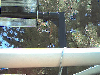
Add the Lexan(r) shelf using "U" bolts. Notice the cross member has angled gussets to keep the bar square and for adding strength. Also note that the bar is held in with conduit clamps so that it can be disassembled for moving.

The water hose is attached with a garden hose adapter and a barb fitting.

Water Jug shelf


Another picture of the gussets and "U" bolts


Shelf holder


Completed PVC frame with water jug shelf - These side pieces were necessary since the tarp would blow around if there was any wind - Without the PVC sides, the tarp would stick to your wet cold body - Ouch!


Completed frame


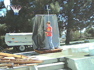
Here's the completed unit before the PVC frame was installed - Someone likes to play in the water ;-)


Hope you get some good ideas from this construction project